Waveguide Dimensions PDF
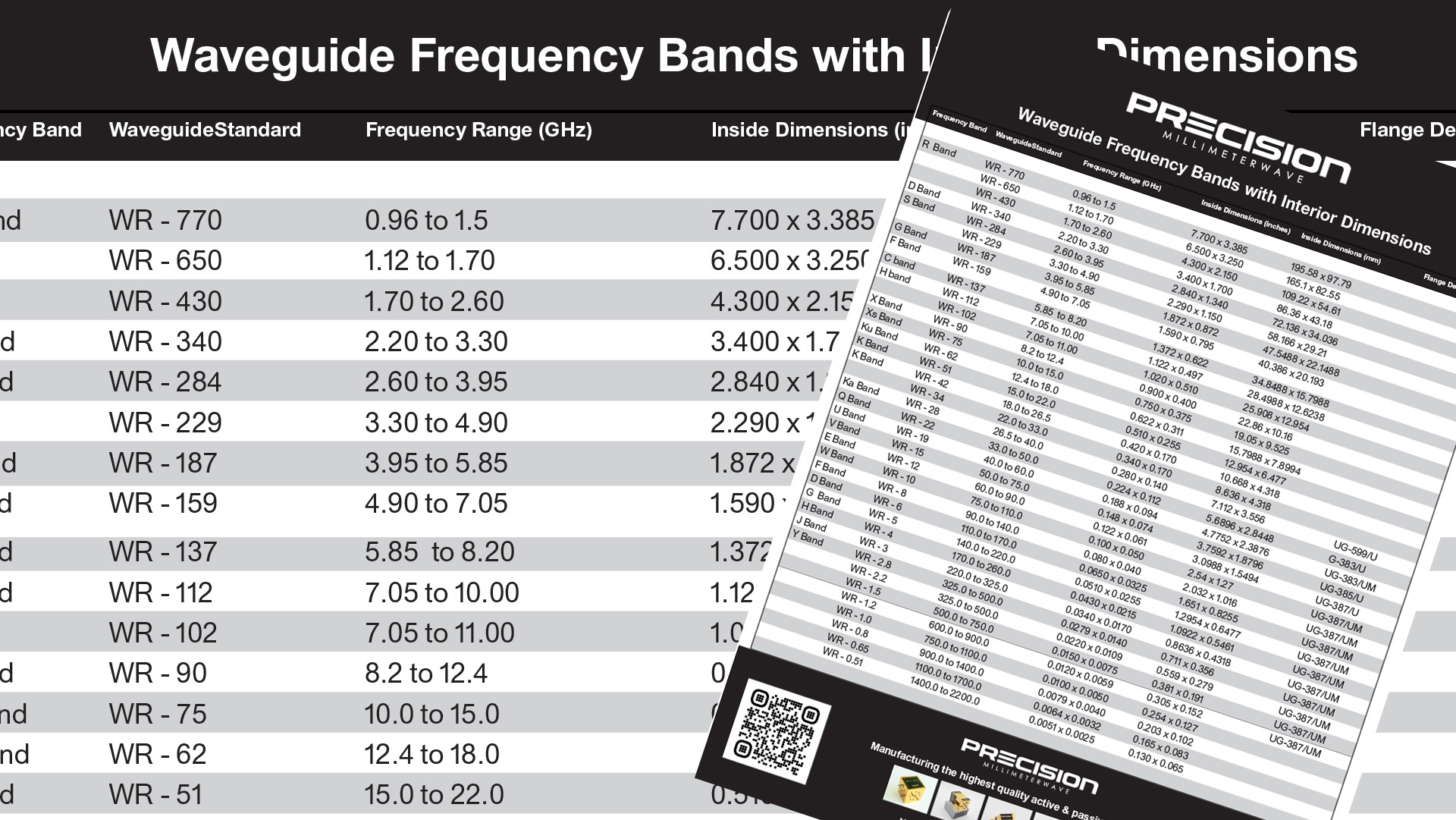
This page covers rectangular waveguide dimensions as per USA standard including frequency ranges, internal dimensions in inches and internal dimensions in millimeters and flange sizes for some bands. It covers standard waveguide dimensions from WR-770 to WR-0.51. This is a handy Waveguide Dimensions PDF that any engineer can use in his or her career as an mmWave engineer.
This chart is in poster size, so if you need to print is made for printing regular paper size or up to a 36″ x 47″ size in hi resolution.
Note:
• The “WR” designation stands for Rectangular Waveguides
• The Number that follows “WR” is the width of the waveguide opening in mils, divided by 10. For Example WR-650 means a waveguide whose cross section width is 6500 mils.
• The waveguide width determines the lower cutoff frequency and is equal (ideally) to ½ wavelength of the lower cutoff frequency
Waveguide Dimensions PDF Chart
Waveguide Dimensions PDF chart includes the following in this sequence below:
Frequency Band
WR Standard
Frequency Range (GHz)
Inside Dimensions (inches)
Inside Dimensions (mm)
Flange Designation
R Band
WR – 770
0.96 to 1.5
7.700 x 3.385
195.58 x 97.79
WR – 650
1.12 to 1.70
6.500 x 3.250
165.1 x 82.55
WR – 430
1.70 to 2.60
4.300 x 2.150
109.22 x 54.61
D Band
WR – 340
2.20 to 3.30
3.400 x 1.700
86.36 x 43.18
S Band
WR – 284
2.60 to 3.95
2.840 x 1.340
72.136 x 34.036
WR – 229
3.30 to 4.90
2.290 x 1.150
58.166 x 29.21
G Band
WR – 187
3.95 to 5.85
1.872 x 0.872
47.5488 x 22.1488
F Band
WR – 159
4.90 to 7.05
1.590 x 0.795
40.386 x 20.193
C band
WR – 137
5.85 to 8.20
1.372 x 0.622
34.8488 x 15.7988
H band
WR – 112
7.05 to 10.00
1.122 x 0.497
28.4988 x 12.6238
WR – 102
7.05 to 11.00
1.020 x 0.510
25.908 x 12.954
X Band
WR – 90
8.2 to 12.4
0.900 x 0.400
22.86 x 10.16
Xs Band
WR – 75
10.0 to 15.0
0.750 x 0.375
19.05 x 9.525
Ku Band
WR – 62
12.4 to 18.0
0.622 x 0.311
15.7988 x 7.8994
K Band
WR – 51
15.0 to 22.0
0.510 x 0.255
12.954 x 6.477
K Band
WR – 42
18.0 to 26.5
0.420 x 0.170
10.668 x 4.318
WR – 34
22.0 to 33.0
0.340 x 0.170
8.636 x 4.318
Ka Band
WR – 28
26.5 to 40.0
0.280 x 0.140
7.112 x 3.556
UG-599/U
Q Band
WR – 22
33.0 to 50.0
0.224 x 0.112
5.6896 x 2.8448
G-383/U
U Band
WR – 19
40.0 to 60.0
0.188 x 0.094
4.7752 x 2.3876
UG-383/UM
V Band
WR – 15
50.0 to 75.0
0.148 x 0.074
3.7592 x 1.8796
UG-385/U
E Band
WR – 12
60.0 to 90.0
0.122 x 0.061
3.0988 x 1.5494
UG-387/U
W Band
WR – 10
75.0 to 110.0
0.100 x 0.050
2.54 x 1.27
UG-387/UM
F Band
WR – 8
90.0 to 140.0
0.080 x 0.040
2.032 x 1.016
UG-387/UM
D Band
WR – 6
110.0 to 170.0
0.0650 x 0.0325
1.651 x 0.8255
UG-387/UM
G Band
WR – 5
140.0 to 220.0
0.0510 x 0.0255
1.2954 x 0.6477
UG-387/UM
H Band
WR – 4
170.0 to 260.0
0.0430 x 0.0215
1.0922 x 0.5461
UG-387/UM
J Band
WR – 3
220.0 to 325.0
0.0340 x 0.0170
0.8636 x 0.4318
UG-387/UM
Y Band
WR – 2.8
325.0 to 500.0
0.0279 x 0.0140
0.711 x 0.356
UG-387/UM
WR – 2.2
325.0 to 500.0
0.0220 x 0.0109
0.559 x 0.279
UG-387/UM
WR – 1.5
500.0 to 750.0
0.0150 x 0.0075
0.381 x 0.191
UG-387/UM
WR – 1.2
600.0 to 900.0
0.0120 x 0.0059
0.305 x 0.152
UG-387/UM
WR – 1.0
750.0 to 1100.0
0.0100 x 0.0050
0.254 x 0.127
WR – 0.8
900.0 to 1400.0
0.0079 x 0.0040
0.203 x 0.102
WR – 0.65
1100.0 to 1700.0
0.0064 x 0.0032
0.165 x 0.083
WR – 0.51
1400.0 to 2200.0
0.0051 x 0.0025
0.130 x 0.065
Download the Waveguide Chart PDF
Rectangular Waveguide Dimensions Chart with millimeter and inches conversion ready for download.
Download our waveguide chart. If you need any waveguide products please contact Precision MMW. We are one of the worlds leading millimeter wave manufacturing and testing companies. Our active and passive component products are expanding rapidly.
Download Waveguide Dimensions PDF
Other RF News, Information & Resources


About Precision Millimeter Wave
We are a growing microwave & millimeter wave manufacturing & engineering company of parts, sub-assemblies and more for both passive & active based components.
Contact us for your needs.


