Understanding Waveguide Bends
Waveguide bends are a fundamental component to microwave RF and millimeter wave applications. This post gives some basis understanding of what waveguide bends are and what they do.
What is a waveguide bend?
Waveguide bends are used in a variety of applications to direct high frequency signals propagating through waveguides. By carefully designing the shape of the waveguide bend, engineers can control the direction of signal propagation with minimal loss, reflection and distortion.
One common application for waveguide bends is in directing microwave signals from one point to another. In this application, waveguide bends are used to change the direction of signal propagation without introducing significant losses or distortions. By using waveguide bends, engineers can ensure that microwave signals are directed where they need to go with minimal interference.
Waveguide bends can also be used in optical applications. In this case, waveguide bends are used to change the direction of radio signals inside a medium. By using waveguide bends, engineers can ensure that optical signals are directed where they need to go with minimal interference.
Waveguide bends are an essential tool for engineers working with high frequency signals.
What are the two types of waveguide bends?
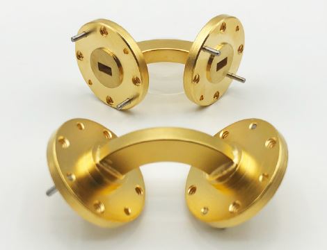
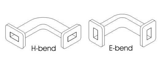
There are two types of waveguide bends: e-bends and h-bends. Waveguide bends are devices that are used to change the direction of wave propagation in a waveguide.
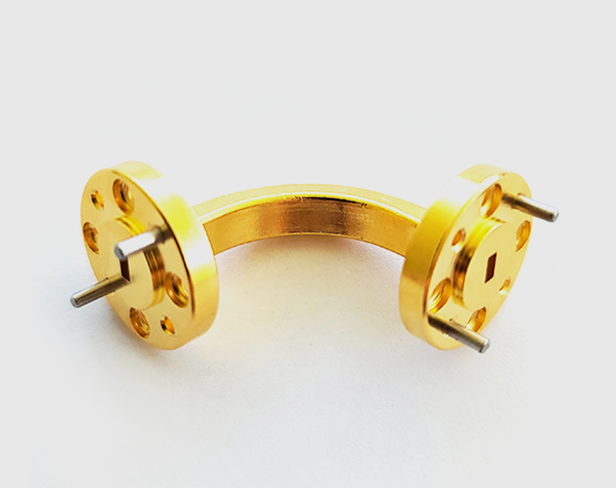
E-bend waveguides are manufactured to have a precise bend degree, typically 90 degrees, 45 degrees, or 30 degrees. They are made by precision machining the waveguide to the desired degree of bend.
H-bend waveguides are also manufactured to have a precise bend degree, but they use a different method to achieve this. Instead of being machined, they are formed by heating and bending the waveguide material. This allows for more accurate manufacturing tolerances and results in a smoother bend.
Specialty microwave and millimeter wave custom waveguide bends are sometimes needed to meet the design specifications of a particular application. These bends can be made to any degree, and are usually designed using computer simulations to ensure that they will meet the needs of the system.
Waveguide bends are an essential part of many microwave and millimeter wave systems, and their performance is crucial to the overall performance of the system. By choosing the right type of waveguide bend for your application, you can ensure that your system will operate at its best.
Waveguide E bends: What is an E-Bend Waveguide?
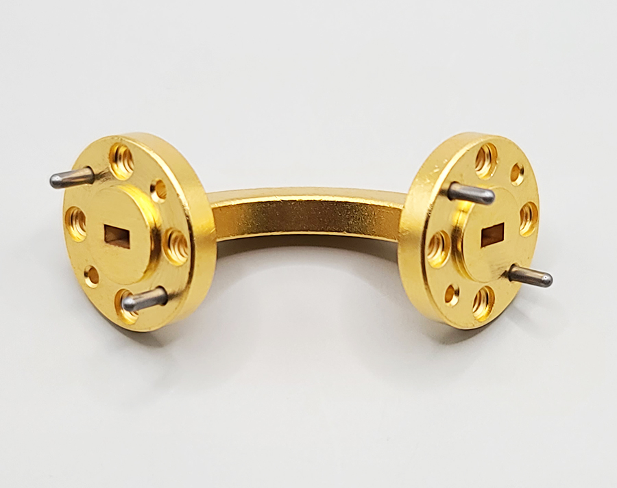
An e-bend is a type of waveguide bend in which the wider part of the waveguide tube is bent to form the bend. This type of bend changes or distorts the electric field (E-field) of the propagating signal, which can cause reflections if not designed properly. In order to reduce reflections, e-bends should have a radius that is greater than two wavelengths of the signal. e-bends are commonly used in microwave and millimeter wave applications because they provide good control over the propagation of signals.
Waveguide H bends: What is an H-Bend Waveguide?
An h-bend is a type of waveguide bend that alters the propagating signal’s H-field (magnetic field). To minimize reflections, it’s important that the h-bend radius be greater than two wavelengths of the signal. This ensures a smooth change in direction of the waveguide axis, while keeping the axis parallel to the direction of transverse (magnetic) polarization. H-bends are commonly used in telecommunications and other microwave and millimeter wave systems where it’s necessary to change the direction of a signal without compromising its quality.
What is the minimum bend radius of any waveguide?
When selecting a waveguide bend, the size of the waveguide and the type of flange must be selected. The most common angles are 30, 45, and 90 degrees, but custom angles can be requested. The selection depends on the frequency you plan to use the waveguide bend. The size and type of flange will depend on the frequency you plan to use the waveguide bend. Custom angles and sizes are available upon request.
What plating is typical for waveguide bends?
There are many different materials that can be used for plating waveguide bends, depending on the desired application. Gold is a common choice, but other materials such as rhodium, brass, aluminum, and stainless steel can also be used. Each of these materials has different properties that can affect the RF signal in different ways. Therefore, it is important to choose the right material for the specific application. In general, gold is a good choice for most applications because it has low loss and high conductivity. Rhodium is another good choice for high-quality applications where loss needs to be minimized. For applications where weight or cost is a concern, aluminum or stainless steel may be a better choice. Ultimately, the best material for plating waveguide bends depends on the specific application and requirements.
Understanding Waveguide Bends by Precision MMW Waveguide Bends
At Precision Millimeter Wave, we pride ourselves on being a quality supplier of RF components and systems. Our team of experienced engineers have worked in the defense contracting and fortune 500 RF industries, so we know the importance of having quality suppliers and parts. We value every single client and are dedicated to providing the best possible service. Whether you need a simple waveguide or a complex RF prototype test system, we can help. Contact us today to learn more about our products and services.
Other RF News, Information & Resources


About Precision Millimeter Wave
We are a growing microwave & millimeter wave manufacturing & engineering company of parts, sub-assemblies and more for both passive & active based components.
Contact us for your needs.


